1. What is the difference between Firmware and Software?
Firmware is the program running inside the relay, which is responsible for all
relay protection and control elements. Software is the program running on the
PC, which is used to communicate with the relay and provide relay control
remotely in a user friendly format.
2. How can I obtain copies of the latest manual and PC software?
I need it now!:via the GE Multilin website athttp://www.GEindustrial.com/
multilin
I guess I can wait:fax a request to the GE Multilin Literature department at
(905) 201-2113
3. Cannot communicate through the front port (RS232).
Check the following settings:
• Communication Port (COM1, COM2, COM3 etc.) on PC or PLC
• Parity settings must match between the relay and the master (PC or PLC)
• Baud rate setting on the master (PC or PLC) must match RS232 baud
rate on the 369 relay.
• Cable has to be a straight through cable, do not use null modem cables
where pin 2 and 3 are transposed
• Check the pin outs of RS232 cable (TX - pin 2, RX - pin 3, GND - pin 5)
4. Cannot communicate with RS485.
Check the following settings:
• Communication Port (COM1, COM2, COM3 etc.) on PC or PLC
• Parity settings must match between the relay and the master (PC or PLC)
• Baud rate must match between the relay and the master
• Slave address polled must match between the relay and the master
• Is terminating filter circuit present?
• Are you communicating in half duplex? (369 communicates in half
duplex mode only)
• Is wiring correct? (“+” wire should go to “+” terminal of the relay, and “–”
goes to “–” terminal)
• Is the RS485 cable shield grounded? (shielding diminishes noise from
external EM radiation)
Check the appropriate communication port LED on the relay. The LED should
be solidly lit when communicating properly. The LED will blink on and off when
the relay has communication difficulties and the LED will be off if no activity
detected on communication lines.
5. Can the 4 wire RS485 (full duplex) be used with 369?
No, the 369 communicates in 2-wire half duplex mode only. However, there
are commercial RS485 converters that will convert a 4 wire to a 2 wire system.
6. Cannot store setpoint into the relay.
Check and ensure the ACCESS switch is shorted, and check for any PASSCODE
restrictions.
7. The 369 relay displays incorrect power reading, yet the power system is
balanced. What could be the possible reasons?
It is highly possible that the secondary wiring to the relay is not correct.
Incorrect power can be read when any of the A, B, or C phases are swapped, a
CT or VT is wired backwards, or the relay is programmed as ABC sequence
when the power system is actually ACB and vice versa. The easiest way to
verify is to check the voltage and the current phasor readings on the 369 relay
and ensure that each respective voltage and current angles match.
8. What are the merits of a residual ground fault connection versus a core
balance connection?
The use of a zero sequence (core balance) CT to detect ground current is
recommended over the G/F residual connection. This is especially true at
motor starting. During across-the-line starting of large motors, care must be
taken to prevent the high inrush current from operating the ground element
of the 369. This is especially true when using the residual connection of 2 or 3
CTs.
In a residual connection, the unequal saturation of the current transformers,
size and location of motor, size of power system, resistance in the power
system from the source to the motor, type of iron used in the motor core &
saturation density, and residual flux levels may all contribute to the
production of a false residual current in the secondary or relay circuit. The
common practice in medium and high voltage systems is to use low
resistance grounding. By using the “doughnut CT” scheme, such systems offer
the advantages of speed and reliability without much concern for starting
current, fault contribution by the motor, or false residual current.
When a zero sequence CT is used, a voltage is generated in the secondary
winding only when zero sequence current is flowing in the primary leads.
Since virtually all motors have their neutrals ungrounded, no zero sequence
current can flow in the motor leads unless there is a ground fault on the motor
side.
9. Can I use an 86 lockout on the 369?
Yes, but if an external 86 lockout device is used and connected to the 369,
ensure the 369 is resetpriorto attempting to reset the lockout switch. If the
369 is still tripped, it will immediately re-trip the lockout switch. Also, if the
lockout switch is held reset, the high current draw of the switch coil may
cause damage to itself and/or the 369 output relay.
10. Can I assign more than one output relay to be blocked when using Start
Inhibits?
Yes, but keep in mind that if two output relays are wired in series to inhibit a
start it is possible that another element could be programmed to control one
or both of the relays. If this is happening and the other element is
programmed with a longer delay time, this will make it seem as if the Start
Inhibit is not working properly when in fact, it is.
11. Can I name a digital input?
Yes. By configuring the digital input as "General" a menu will appear that will
allow naming.
12. Can I apply an external voltage to the digital inputs on the 369?
No. The 369 uses an internal voltage to operate the digital inputs. Applying an
external voltage may cause damage to the internal circuitry.
13. Can I upload setpoint files from previous versions to the latest version of
firmware?
Yes, with the exception of setpoint files from versions 1.10 and 1.12.
Unfortunately these setpoint files must be rewritten, as they are not
compatible.
14. What method does the 369 use to calculate current unbalance?
The 369 uses the NEMA method. Previous revisions of the 369 manual have
incorrectly included a functional test that measured the ratio of negative
sequence current to positive sequence current. The NEMA method is as
follows:
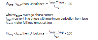
To prevent nuisance trips/alarms on lightly loaded motors when a much
larger unbalance level will not damage the rotor, the unbalance protection will
automatically be defeated if the average motor current is less than 30% of the
full load current (IFLA) setting.
15. I need to update the options for my 369/RRTD in the field, can I do this?
Yes. All options of the 369/RRTD can be turned on or added in the field. To do
this contact the factory.
16. Can I test my output relays?
Yes, but keep in mind that the output relays cannot be forced into a different
state while the motor is running.
17. Is the communication interface for Profibus RS232 or RS485?
It is RS485. The 9-pin connector on the rear of the 369 is the connector used
by the manufacturer of the Profibus card and although it is a DB-9, the
electrical interface is RS485.
18. Can I use the options enabler code to upgrade my 369 in the field to get the
Profibus option?
Yes, but keep in mind that there is a Profibus card that is required and is not
installed in units that were not ordered from the factory with the Profibus
option.
19. Can the 369 be used as a remote unit, similar to the 269 remote?
Yes. Every 369 can be used as remote. When ordering the 369, an external 15
foot cable must be ordered.
20. Can the RRTD module be used as a standalone unit?
Yes. The RRTD unit with the IO option, has 4 output relays, 6 digital inputs and
4 analog outputs. With this option the RRTD can provide temperature
protection.
21. Why is there a filter ground and a safety ground connection? Why are they
separate?
The safety ground ensures operator safety with regards to hazardous shocks;
the filter ground protects the internal electronic circuitry from transient noise.
These two grounds are separated for hi-pot (dielectric strength) testing
purposes. Both grounds should be tied to the ground bus external to the relay.
22. 369 doesn't communicate with ethernet after change in IP address, what
should I do?
Cycle the power supply to the 369. In order to make the new IP address active
the power supply of the 369 must be recycled after changing or setting the IP
address of the relay.
1. Can I send a 269 setpoint file to a 369 relay?
Yes. Using the 369 PC program, a 269 setpoint file can be sent to the
369. Note: any settings/features that are not in the 269 setpoint file will
not be changed on the 369 unit and will be set as default values. All
setpoints should be confirmed before operating the relay.
2. Can I use an 86 lockout on the 369?
Yes, but If an external 86 lockout device is used and connected to the
369, ensure that the 369 is reset prior to attempting to reset the lockout
switch. If the 369 is still tripped, it will immediately retrip the lockout
switch. Also, if the lockout switch is held reset, the high current draw
of the lockout switch coil may cause damage to itself and/or the 369
output relay.
3. Can I assign more than one output relay to be blocked when
using Start Inhibits?
Yes, but keep in mind that if two output relays are wired in series to
inhibit a start, it is possible that another element could be programmed
to control one or both of the relays. If this is happening and the other
element is programmed with a longer delay time, this will make it seem
as if the Start Inhibit is not working properly when in fact, it is.
4. Can I connect three voltage transformers to achieve a delta
configuration in the 369?
Yes, but it is unnecessary since the 369 will calculate Vca based on
the measured Vab and Vcb.
5. Can I name a digital input?
Yes. By configuring the digital input as "General", a menu will appear
that will allow naming.
6. Can I apply an external voltage to the digital inputs on the 369?
No. The 369 uses an internal voltage to operate the digital inputs.
Applying an external voltage may cause damage to the internal
circuitry.
7. No display, no characters on the display, but there is a backlight.
Press the HELP key, when all the LEDs are illuminated, press ENTER
to automatically set the contrast to 145. You may also communicate
with the relay using the 369 PC program to check the contrast setting.
8. What are the merits of a residual ground fault connection versus
a core balance connection?
The use of a zero sequence (core balance) CT to detect ground
current is recommended over the G/F residual connection. This is
especially true at motor starting. During across-the-line starting of
large motors, care must be taken to prevent the high inrush current
from operating the ground element of the 369. This is especially true
when using the residual connection of 2 or 3 CTs. In a residual
connection, the unequal saturation of the current transformers, size
and location of motor, size of power system, resistance in the power
system from the source to the motor, type of iron used in the motor
core and saturation density, and residual flux levels may all contribute
to the production of a false residual current in the secondary or relay
circuit. The common practice in medium and high voltage systems is
to use low resistance grounding. By using the doughnut CT scheme,
such systems offer the advantages of speed and reliability without
much concern for starting current, fault contribution by the motor, or
false residual current. When a zero sequence CT is used, a voltage is
generated in the secondary winding only when zero sequence current
is flowing in the primary leads. Since virtually all motors have their
neutrals ungrounded, no zero sequence current can flow in the motor
leads unless there is a ground fault on the motor side.
9. Can I upload setpoint files from previous versions to the latest
version of firmware?
Yes, with the exception of setpoint files from versions 1.10 to 1.12.
Unfortunately, these setpoint files must be rewritten, as they are not
compatible.
10. Can I use the learned values with motors that have start times
faster than 500 milliseconds?
Yes, but keep in mind that for motors that have start times faster than
500 milliseconds, there will not be any data for the very first start. For
following starts, the 369 will be able to provide data based on previous
start information.
11. I need to update the options for my 369/RRTD in the field, can I do
this?
Yes. All options of the 369/RRTD can be turned on or added in the
field except for the Profibus and Ethernet options for the 369. To do
this, contact the factory.
12. Can the 369 be used as a remote display unit, similar to the 269
remote?
Yes. Every 369 can be used as remote. When ordering the 369, an
external 15 foot cable must be ordered.
13. Is there a limit to the lead length of my RTD?
Yes. Correct operation will occur providing all three wires are of the
same length and the resistance of each lead is not greater than 25% of
the RTD 0°C resistance. This can be accomplished by using identical
lengths of the same type of wire. If 10 ohm copper RTD's are used,
special care should be taken to keep the lead resistance as low as
possible.
14. I cannot store setpoints into the relay.
Check and make sure the ACCESS switch is shorted (terminals 57 and
58). Also, check for any PASSCODE restrictions from page S1
Setpoints / 369 Setup / Setpoint Access.
15. Can the RRTD module be used as a standalone unit?
Yes. The RRTD unit with the IO option has 4 output relays, 6 digital
inputs, and 4 analog outputs. With this option, the RRTD can provide
temperature protection.
16. The 369 relay displays a high unbalance reading (or wrong power
reading), yet the power system is balanced, what could be the
possible reasons?
It is highly possible that the secondary wiring to the relay is not correct.
High unbalance (and wrong power) can be read when any of the A, B,
or C phases are swapped, or the relay is programmed as ABC
sequence when the power system is actually ACB and vice versa. The
easiest way to verify is to check the voltage and the current phasor
readings on the 369 relay and make sure that each of the respective
voltage and current angles match.
17. Can 4-wire RS485 (full duplex) be used with 369?
No, the 369 communicates in 2-wire half-duplex mode only. However,
there are commercial RS485 converters that will convert a 4-wire to a
2-wire system.
版权所有:西电通用电气自动化有限公司 陕ICP备13001388号 技术支持:西安博达软件